
Acoustic cameras have become an important tool for modern industrial inspection. Unlike traditional ultrasonic detectors that mainly provide audio signals or numerical readings, an acoustic imaging camera can visualize sound sources directly on a screen. This allows engineers to see where a sound is coming from, compare its intensity and record visual evidence for maintenance decisions.
In the previous article, we introduced what an acoustic camera is. Now, we will take one step further into practical field applications and explain how acoustic cameras work on site, why different sound field display modes matter and how real sound field and computed sound field modes can support more reliable inspection results.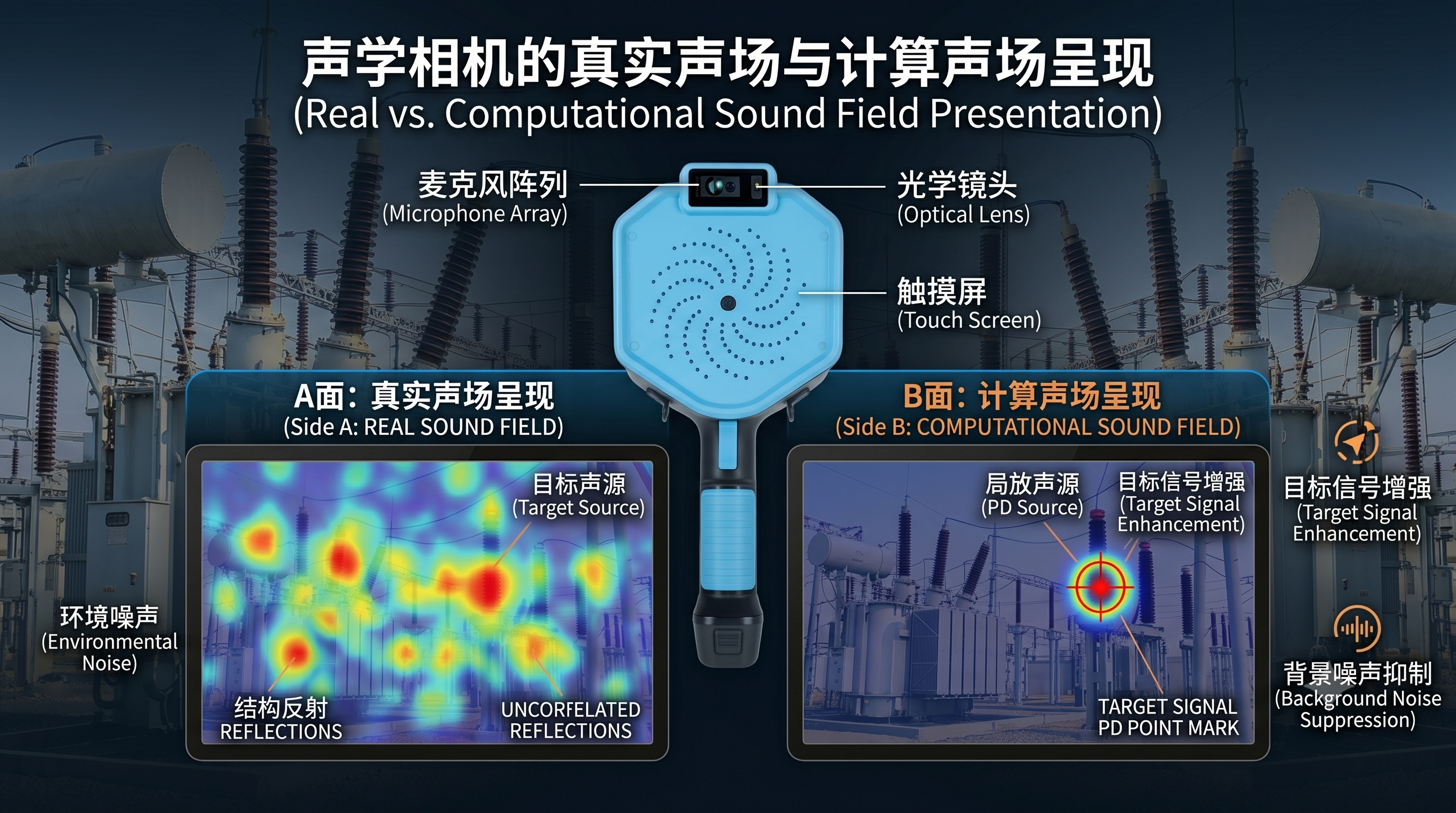
The basic principle of an acoustic camera is sound source localization. Click here to learn more.
An acoustic camera uses a microphone array to capture sound signals from the testing area. When the same sound wave reaches different microphones, it arrives at slightly different times and phases. By analyzing these time and phase differences, the system can estimate the direction and position of the sound source.
After the sound source position, acoustic intensity and frequency information are calculated, the system generates a spatial sound energy distribution map. This sound energy map is then overlaid on the optical image captured by the built-in camera. The result is an acoustic image, often displayed as a color heatmap over the real-world visual scene.
This is why an acoustic camera can help engineers identify invisible problems such as partial discharge, compressed air leakage, gas leakage and abnormal mechanical noise.
Real sound field visualization refers to the direct presentation of the acoustic energy distribution detected by the microphone array. It is closer to the original sound field captured at the testing site.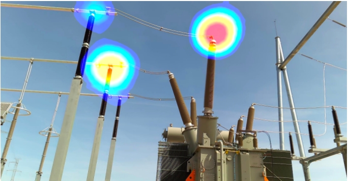
In a typical real sound field display, the acoustic camera processes the captured sound data and limits the dynamic range of the acoustic image. By narrowing the display range, the camera can highlight stronger sound sources and make the image easier to read.
This approach is simple, direct and widely used across many acoustic camera systems. For relatively quiet environments, or when the target sound source is clearly stronger than the background noise, real sound field visualization can provide fast and intuitive results.
However, industrial environments are rarely ideal.
In real inspection scenarios, acoustic imaging can be affected by many environmental factors.
First, sound waves are mechanical waves. Their propagation can be influenced by airflow, wind, obstacles, reflections and the structure of the testing environment. In substations, factories, compressor rooms or outdoor industrial sites, the acoustic signal may be disturbed before it reaches the microphone array.
Second, background noise can make sound source localization more difficult. Motors, fans, pumps, transformers, valves and other equipment may generate continuous or intermittent noise. These noises can overlap with the target signal and reduce the clarity of the acoustic image.
Third, multiple unrelated sound sources may exist in the same field of view. When several independent sound sources appear at the same time, the acoustic camera may display a wider or more complex sound field. This can make it harder for users to quickly identify the most important source.
For these reasons, real sound field visualization may not always provide the most stable or user-friendly image, especially in complex industrial environments.
Computed sound field, also known as sound source marking or enhanced sound source visualization, is an algorithm-based display mode built on top of the real sound field.
Instead of simply showing the original acoustic energy distribution, computed sound field applies additional signal processing, filtering and multi-dimensional analysis. The goal is to identify the target sound source more stably and reduce the influence of environmental noise, airflow disturbance and unrelated sound sources.
In practical terms, computed sound field helps the acoustic camera present a cleaner and more focused sound source marker. It does not replace the real sound field; rather, it enhances the useful signal so that field engineers can interpret the result more easily.
This is especially valuable when the inspection target is weak, intermittent or surrounded by background noise.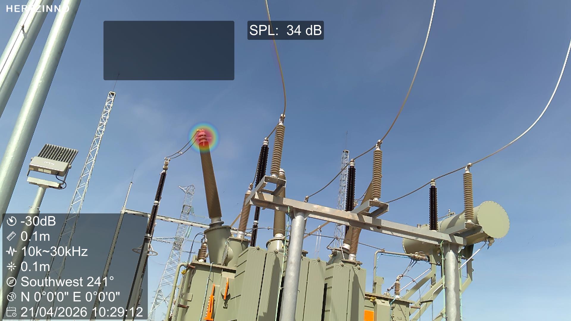
Partial discharge detection is one of the most important applications of acoustic cameras in the power industry.
Partial discharge may occur in substations, switchgear, transformers, cable terminals and other high-voltage electrical assets. In many cases, the ultrasonic signal generated by partial discharge can be weak or intermittent. The site may also contain transformer noise, corona noise, wind noise or other electrical and mechanical sound sources.
In such environments, relying only on the real sound field may make it difficult to distinguish the target discharge signal from surrounding interference.
Computed sound field can improve the user experience by making the target sound source more stable and easier to locate. Through advanced filtering and algorithmic processing, the acoustic camera can help suppress non-target interference and highlight the sound source that is more relevant to the inspection task.
For field users, this means faster localization, clearer visual feedback and more confidence when making maintenance decisions.
Both modes are useful, but they are suitable for different inspection scenarios.
Real sound field mode is suitable when users want to observe the original acoustic energy distribution. It is useful for understanding the overall sound environment, checking multiple sound sources and reviewing how sound energy is distributed across the testing area.
Computed sound field mode is suitable when users need a clearer target marker. It is especially helpful in noisy industrial sites, partial discharge inspection, gas leak localization and other scenarios where the target signal may be affected by interference.
In simple terms, real sound field shows what the acoustic camera hears more directly, while computed sound field helps users see the most relevant sound source more clearly.
Acoustic cameras are used across many industrial scenarios, including:
Partial discharge inspection in substations and switchgear
Compressed air leak detection in manufacturing plants
Gas leak localization in oil, gas and chemical facilities
Mechanical fault diagnosis for motors, bearings, pumps and fans
Electrical room and data center inspection
Predictive maintenance for critical equipment
In these applications, the inspection environment, target frequency, sound intensity and background noise level can vary greatly. A flexible sound field display strategy allows engineers to adapt the acoustic camera to the actual testing site instead of relying on a single fixed display method.
HERTZINNO acoustic cameras are designed to help engineers visualize sound sources in complex industrial environments. By combining microphone array technology, acoustic imaging, optical image overlay and intelligent signal processing, HERTZINNO provides practical tools for partial discharge detection, gas leak localization and industrial fault inspection.
For field inspection teams, the key value of an acoustic camera is not only to “hear” the sound, but also to “see” the source clearly. Real sound field visualization helps restore the acoustic condition of the site, while computed sound field helps highlight the target signal and reduce the impact of interference.
Together, these two modes can make acoustic imaging more effective, more intuitive and more suitable for real industrial applications.
Real sound field and computed sound field are two important visualization approaches in acoustic camera applications.
Real sound field provides a direct view of acoustic energy distribution, while computed sound field uses algorithmic processing to improve target sound source marking. In clean environments, real sound field can be fast and intuitive. In complex field conditions, computed sound field can help users obtain a clearer and more stable result.
For power utilities, industrial plants and maintenance teams, choosing the right sound field mode can improve inspection efficiency, reduce uncertainty and support better maintenance decisions.
With the right acoustic camera and the right visualization mode, invisible acoustic problems can become visible, measurable and easier to solve.


